-
Part Symbol
-
Footprint
-
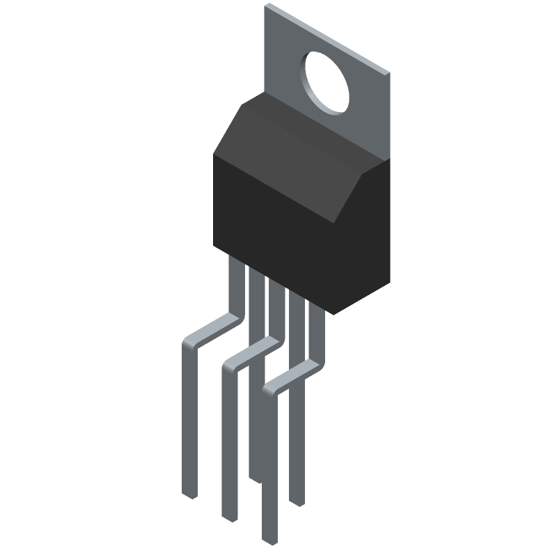
3D Model
Available Download Formats
By downloading CAD models, you agree to our Terms & Conditions and Privacy Policy
0.9A BUF OR INV BASED PRPHL DRVR, PZFM5, VERTICAL, PENTAWATT-5
Tip: Data for a part may vary between manufacturers. You can filter for manufacturers on the top of the page next to the part image and part number.
VN02H by STMicroelectronics is a Peripheral Driver.
Peripheral Drivers are under the broader part category of Drivers And Interfaces.
A driver controls the current or voltage delivered to components like LCDs or motors, while an interface component connects systems for data transfer and control. Read more about Drivers And Interfaces on our Drivers And Interfaces part category page.
| Part # | Distributor | Description | Stock | Price | Buy | |
|---|---|---|---|---|---|---|
|
|
Bristol Electronics | 94 |
|
RFQ |
By downloading CAD models, you agree to our Terms & Conditions and Privacy Policy
|
|
VN02H
STMicroelectronics
Buy Now
Datasheet
|
Compare Parts:
VN02H
STMicroelectronics
0.9A BUF OR INV BASED PRPHL DRVR, PZFM5, VERTICAL, PENTAWATT-5
Select a part to compare: |
| Rohs Code | Yes | |
| Part Life Cycle Code | Obsolete | |
| Ihs Manufacturer | STMICROELECTRONICS | |
| Part Package Code | ZFM | |
| Package Description | VERTICAL, PENTAWATT-5 | |
| Pin Count | 5 | |
| Reach Compliance Code | compliant | |
| ECCN Code | EAR99 | |
| HTS Code | 8542.39.00.01 | |
| Samacsys Manufacturer | STMicroelectronics | |
| Built-in Protections | TRANSIENT; OVER CURRENT; THERMAL; UNDER VOLTAGE | |
| Driver Number of Bits | 1 | |
| Interface IC Type | BUFFER OR INVERTER BASED PERIPHERAL DRIVER | |
| JESD-30 Code | R-PZFM-T5 | |
| JESD-609 Code | e3 | |
| Number of Functions | 1 | |
| Number of Terminals | 5 | |
| Output Current Flow Direction | SOURCE | |
| Output Current-Max | 3 A | |
| Output Peak Current Limit-Nom | 0.9 A | |
| Package Body Material | PLASTIC/EPOXY | |
| Package Code | ZIP | |
| Package Equivalence Code | ZIP5,.15,.2,67TB | |
| Package Shape | RECTANGULAR | |
| Package Style | FLANGE MOUNT | |
| Qualification Status | Not Qualified | |
| Supply Voltage-Max | 36 V | |
| Supply Voltage-Min | 5 V | |
| Surface Mount | NO | |
| Terminal Finish | MATTE TIN | |
| Terminal Form | THROUGH-HOLE | |
| Terminal Pitch | 1.7 mm | |
| Terminal Position | ZIG-ZAG | |
| Turn-off Time | 30 µs | |
| Turn-on Time | 20 µs |
A good PCB layout for VN02H involves keeping the high-current paths short and wide, using a solid ground plane, and placing decoupling capacitors close to the IC. A 4-layer PCB with a dedicated power plane is recommended.
To ensure reliable operation in high-temperature environments, ensure good thermal dissipation by using a heat sink, and follow the recommended thermal design guidelines. Also, consider using a thermistor to monitor the temperature and adjust the VN02H's operation accordingly.
For EMI and EMC compliance, ensure proper PCB layout, use a shielded enclosure, and add EMI filters or chokes as needed. Also, follow the recommended layout and grounding guidelines to minimize radiated emissions.
To troubleshoot and debug issues with the VN02H, use a logic analyzer or oscilloscope to monitor the signals, check the power supply and voltage regulator, and verify the PCB layout and component placement. Consult the datasheet and application notes for specific guidance.
The recommended components for the external circuitry include a suitable voltage regulator, decoupling capacitors, and a freewheeling diode. Consult the datasheet and application notes for specific component recommendations and values.