-
Part Symbol
-
Footprint
-
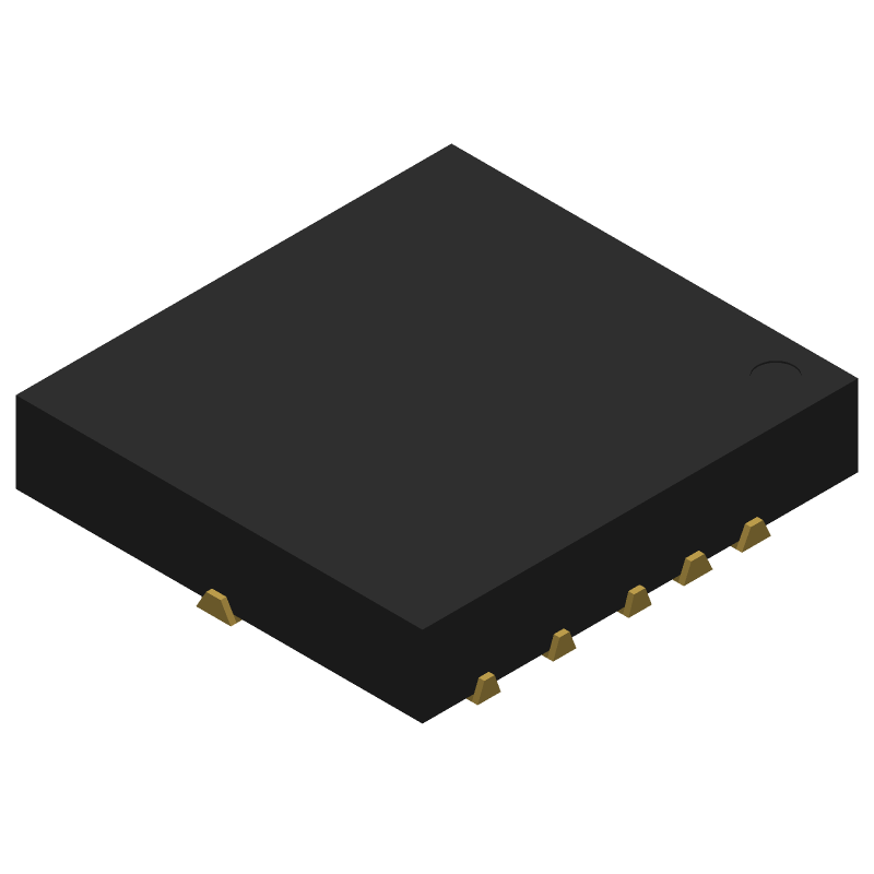
3D Model
Available Download Formats
By downloading CAD models, you agree to our Terms & Conditions and Privacy Policy
36V, 220kHz to 2.2MHz, 4A/6A/8AFully Integrated AutomotiveStep-Down Converters, 17-LFCSP_SS-3.5X3.5X0.70, 17 Pins, -40 to 125C
Tip: Data for a part may vary between manufacturers. You can filter for manufacturers on the top of the page next to the part image and part number.
MAX20006AFOD/VY+T by Analog Devices Inc is a Switching Regulator or Controller.
Switching Regulator or Controllers are under the broader part category of Power Circuits.
A power circuit delivers electricity in order to operate a load for an electronic device. Power circuits include transformers, generators and switches. Read more about Power Circuits on our Power Circuits part category page.
| Part # | Distributor | Description | Stock | Price | Buy | |
|---|---|---|---|---|---|---|
|
DISTI #
700-MAX20006AFODVY+T
|
Mouser Electronics | Switching Voltage Regulators 36V, 220kHz to 2.2MHz, 4A/6A/8A Fully in RoHS: Compliant | 11695 |
|
$2.8100 / $6.9800 | Buy Now |
|
|
Analog Devices Inc | 36V, 220kHz to 2.2MHz, 4A/6A/8 Min Qty: 1 Package Multiple: 1 | 745 |
|
$2.2500 / $6.9800 | Buy Now |
By downloading CAD models, you agree to our Terms & Conditions and Privacy Policy
|
|
MAX20006AFOD/VY+T
Analog Devices Inc
Buy Now
Datasheet
|
Compare Parts:
MAX20006AFOD/VY+T
Analog Devices Inc
36V, 220kHz to 2.2MHz, 4A/6A/8AFully Integrated AutomotiveStep-Down Converters, 17-LFCSP_SS-3.5X3.5X0.70, 17 Pins, -40 to 125C
Select a part to compare: |
| Rohs Code | Yes | |
| Part Life Cycle Code | Active | |
| Ihs Manufacturer | ANALOG DEVICES INC | |
| Part Package Code | 17-LFCSP_SS-3.5X3.5X0.70 | |
| Pin Count | 17 | |
| Manufacturer Package Code | 17-LFCSP_SS-3.5X3.5X0.70 | |
| Reach Compliance Code | compliant | |
| Date Of Intro | 2018-12-19 | |
| Samacsys Manufacturer | Analog Devices | |
| Analog IC - Other Type | SWITCHING REGULATOR | |
| JESD-609 Code | e3 | |
| Moisture Sensitivity Level | 1 | |
| Peak Reflow Temperature (Cel) | 260 | |
| Terminal Finish | Matte Tin (Sn) | |
| Time@Peak Reflow Temperature-Max (s) | 30 |
This table gives cross-reference parts and alternative options found for MAX20006AFOD/VY+T. The Form Fit Function (FFF) tab will give you the options that are more likely to serve as direct pin-to-pin alternates or drop-in parts. The Functional Equivalents tab will give you options that are likely to match the same function of MAX20006AFOD/VY+T, but it may not fit your design. Always verify details of parts you are evaluating, as these parts are offered as suggestions for what you are looking for and are not guaranteed.
| Part Number | Manufacturer | Composite Price | Description | Compare |
|---|---|---|---|---|
| MAX20006EAFOD/VY+ | Analog Devices Inc | Check for Price | Automotive, 36V, 4A/6A/8A Integrated Step-Down Converters with Integrated Compensation, 17-LFCSP_SS-3.5X3.5X0.70, 17 Pins, -40 to 125C | MAX20006AFOD/VY+T vs MAX20006EAFOD/VY+ |
A good PCB layout for the MAX20006AFOD/VY+T involves keeping the input and output traces short and separate, using a solid ground plane, and placing decoupling capacitors close to the device. A 4-layer PCB with a dedicated power plane and a dedicated ground plane is recommended. Additionally, it's essential to follow the layout guidelines provided in the datasheet and application notes.
The selection of input and output capacitors for the MAX20006AFOD/VY+T depends on the specific application requirements. In general, X5R or X7R ceramic capacitors with a voltage rating of 10V or higher are recommended. The capacitance value should be chosen based on the desired cutoff frequency and the impedance of the input and output signals. A good starting point is to use 1uF to 10uF capacitors for both input and output.
The MAX20006AFOD/VY+T has an operating temperature range of -40°C to +125°C. However, the device's performance may degrade at higher temperatures, and the maximum junction temperature should not exceed 150°C.
The MAX20006AFOD/VY+T requires a single 3.3V or 5V power supply. The device should be powered from a clean, low-noise power source, and the power supply pins should be decoupled with 0.1uF to 1uF capacitors. The bias voltage should be set to the desired level using an external resistor divider network or a dedicated bias voltage source.
The typical startup time for the MAX20006AFOD/VY+T is around 1ms to 2ms, depending on the input voltage and the output load. However, this time can vary depending on the specific application and the device's configuration.