-
Part Symbol
-
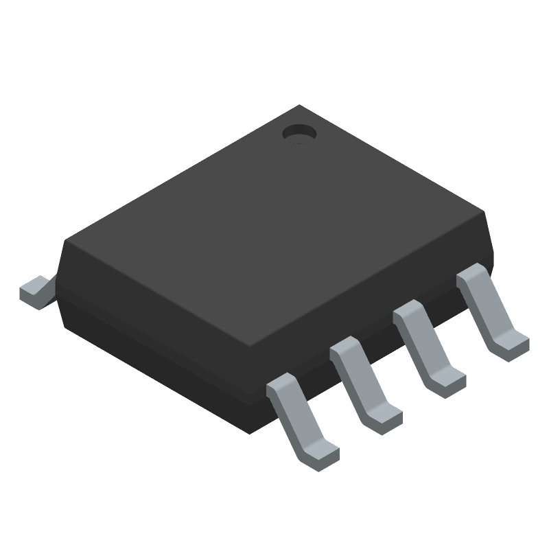
Footprint
-
3D Model
Available Download Formats
By downloading CAD models, you agree to our Terms & Conditions and Privacy Policy
Two-Channel, Low-Power, 3kVRMS and 5kVRMS Digital Isolators, 8-SOIC_N-150_MIL, 8 Pins, -40 to 125C
Tip: Data for a part may vary between manufacturers. You can filter for manufacturers on the top of the page next to the part image and part number.
MAX12930CASA+ by Analog Devices Inc is an Other Signal Circuit.
Other Signal Circuits are under the broader part category of Signal Circuits.
A signal is an electronic means of transmitting information, either as an analog signal with continuous values or a digital signal with discrete values. Signals are used in various systems and networks. Read more about Signal Circuits on our Signal Circuits part category page.
| Part # | Distributor | Description | Stock | Price | Buy | |
|---|---|---|---|---|---|---|
|
DISTI #
700-MAX12930CASA+
|
Mouser Electronics | Digital Isolators 2-Channel, 3.75kVRMS Digital Isolators RoHS: Compliant | 700 |
|
$2.9200 / $7.1800 | Buy Now |
|
|
Analog Devices Inc | 2-Channel, 3.75kVRMS Digital I Package Multiple: 1 | 27969 |
|
$2.3400 / $7.1800 | Buy Now |
By downloading CAD models, you agree to our Terms & Conditions and Privacy Policy
|
|
MAX12930CASA+
Analog Devices Inc
Buy Now
Datasheet
|
Compare Parts:
MAX12930CASA+
Analog Devices Inc
Two-Channel, Low-Power, 3kVRMS and 5kVRMS Digital Isolators, 8-SOIC_N-150_MIL, 8 Pins, -40 to 125C
Select a part to compare: |
| Rohs Code | Yes | |
| Part Life Cycle Code | Active | |
| Ihs Manufacturer | ANALOG DEVICES INC | |
| Part Package Code | 8-SOIC_N-150_MIL | |
| Package Description | SOIC-8 | |
| Pin Count | 8 | |
| Manufacturer Package Code | 8-SOIC_N-150_MIL | |
| Reach Compliance Code | compliant | |
| Date Of Intro | 2016-09-19 | |
| Samacsys Manufacturer | Analog Devices | |
| JESD-609 Code | e3 | |
| Moisture Sensitivity Level | 1 | |
| Peak Reflow Temperature (Cel) | 260 | |
| Terminal Finish | Matte Tin (Sn) | |
| Time@Peak Reflow Temperature-Max (s) | 30 |
A good PCB layout for the MAX12930CASA+ involves keeping the analog and digital grounds separate, using a solid ground plane, and minimizing noise coupling between the analog and digital sections. A 4-layer PCB with a dedicated analog ground plane is recommended. Additionally, place the device close to the analog signal sources and keep the analog signal traces short and shielded.
To optimize the performance of the MAX12930CASA+ in a noisy environment, use a low-pass filter on the analog input signals, use a shielded enclosure, and keep the device away from high-frequency noise sources. Additionally, use a common-mode choke on the power supply lines and decouple the power supply with a 10uF capacitor.
The maximum clock frequency that can be used with the MAX12930CASA+ is 50MHz. However, the actual clock frequency used may be limited by the specific application and the noise environment.
The MAX12930CASA+ can be programmed using the SPI interface. The device has a set of registers that can be written to configure the device for a specific application. The programming sequence involves writing to the control registers, configuring the analog-to-digital converter (ADC), and setting the output format. Refer to the datasheet and the application notes for specific programming examples.
The power consumption of the MAX12930CASA+ depends on the specific application and the clock frequency used. Typically, the device consumes around 20mA of current at a 3.3V supply voltage and a 10MHz clock frequency. However, the actual power consumption may be higher or lower depending on the specific use case.