-
Part Symbol
-
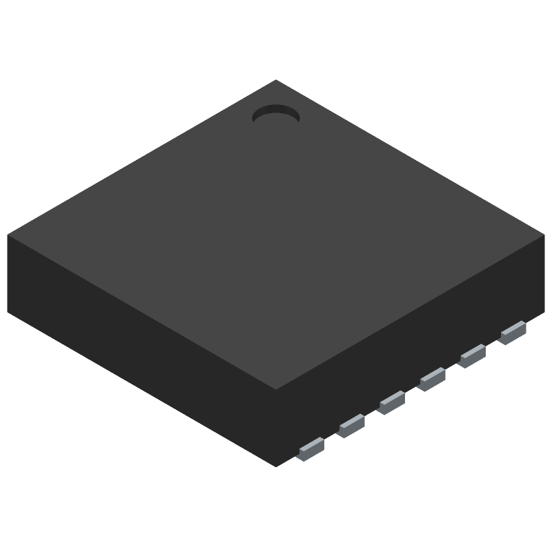
Footprint
-
3D Model
Available Download Formats
By downloading CAD models, you agree to our Terms & Conditions and Privacy Policy
6 GHz RMS Power Detector with Digital Output
Tip: Data for a part may vary between manufacturers. You can filter for manufacturers on the top of the page next to the part image and part number.
LTC5587IDD#PBF by Analog Devices Inc is an Other Telecom IC.
Other Telecom ICs are under the broader part category of Telecommunication Circuits.
A telecommunications circuit transmits and receives information between points. Key components include transmitters, receivers, amplifiers, and multiplexers. Read more about Telecommunication Circuits on our Telecommunication Circuits part category page.
| Part # | Distributor | Description | Stock | Price | Buy | |
|---|---|---|---|---|---|---|
|
DISTI #
50AK3770
|
Newark | Rms Power Detector, -40 To 85Deg C, Ic Function:6 Ghz Rms Power Detector With Digital Output, Supp... more RoHS: Compliant Min Qty: 1 Package Multiple: 1 Date Code: 1 Container: Bulk | 133 |
|
$8.0400 / $15.2500 | Buy Now |
|
DISTI #
505-LTC5587IDD#PBF-ND
|
DigiKey | IC RF DETECT 10MHZ-6GHZ 12DFN Min Qty: 1 Lead time: 13 Weeks Container: Tube |
660 In Stock |
|
$9.6252 / $13.9100 | Buy Now |
|
DISTI #
584-LTC5587IDD#PBF
|
Mouser Electronics | RF Detector 6 GHz RMS Pwr Detector w/ Dig Out RoHS: Compliant | 1323 |
|
$8.0300 / $15.2500 | Buy Now |
|
|
Analog Devices Inc | 6 GHz RMS Pwr Detector w/ Dig Package Multiple: 121 | 374 |
|
$6.4300 / $15.2500 | Buy Now |
|
DISTI #
35217124
|
Verical | RF Detector 10MHz to 6000MHz 6dBm 12-Pin DFN EP Tube RoHS: Compliant Min Qty: 121 Package Multiple: 121 | Americas - 363 |
|
$7.3800 | Buy Now |
|
DISTI #
LTC5587IDD#PBF
|
Richardson RFPD | CONVERTER - ADC RoHS: Compliant Min Qty: 121 | 0 |
|
$8.3000 / $9.1100 | Buy Now |
By downloading CAD models, you agree to our Terms & Conditions and Privacy Policy
|
|
LTC5587IDD#PBF
Analog Devices Inc
Buy Now
Datasheet
|
Compare Parts:
LTC5587IDD#PBF
Analog Devices Inc
6 GHz RMS Power Detector with Digital Output
Select a part to compare: |
| Pbfree Code | No | |
| Rohs Code | Yes | |
| Part Life Cycle Code | Active | |
| Ihs Manufacturer | ANALOG DEVICES INC | |
| Package Description | 3 X 3 MM, LEAD FREE, PLASTIC, DFN-12 | |
| Pin Count | 12 | |
| Manufacturer Package Code | 05-08-1725 | |
| Reach Compliance Code | compliant | |
| Samacsys Manufacturer | Analog Devices | |
| JESD-30 Code | S-PDSO-N12 | |
| JESD-609 Code | e3 | |
| Length | 3 mm | |
| Moisture Sensitivity Level | 1 | |
| Number of Functions | 1 | |
| Number of Terminals | 12 | |
| Operating Temperature-Max | 85 °C | |
| Operating Temperature-Min | -40 °C | |
| Package Body Material | PLASTIC/EPOXY | |
| Package Code | HVSON | |
| Package Shape | SQUARE | |
| Package Style | SMALL OUTLINE | |
| Peak Reflow Temperature (Cel) | 260 | |
| Qualification Status | Not Qualified | |
| Seated Height-Max | 0.8 mm | |
| Supply Voltage-Nom | 3.3 V | |
| Surface Mount | YES | |
| Technology | CMOS | |
| Telecom IC Type | TELECOM CIRCUIT | |
| Temperature Grade | INDUSTRIAL | |
| Terminal Finish | Matte Tin (Sn) | |
| Terminal Form | NO LEAD | |
| Terminal Pitch | 0.45 mm | |
| Terminal Position | DUAL | |
| Time@Peak Reflow Temperature-Max (s) | 30 | |
| Width | 3 mm |
A good PCB layout for the LTC5587IDD#PBF involves keeping the analog and digital grounds separate, using a solid ground plane, and placing the device close to the antenna. Additionally, it's recommended to use a 4-layer PCB with a dedicated layer for the analog ground and another for the digital ground.
To optimize the performance of the LTC5587IDD#PBF in a high-temperature environment, ensure good thermal management by providing adequate heat sinking and airflow. Also, consider using a thermal interface material to improve heat transfer between the device and the heat sink.
The recommended power-up sequence for the LTC5587IDD#PBF is to first apply the analog power supply (AVDD), followed by the digital power supply (DVDD), and finally the enable signal (EN). This sequence helps prevent damage or malfunction.
To troubleshoot issues with the LTC5587IDD#PBF, start by verifying the power supply voltages and ensuring that the device is properly configured. Then, use a logic analyzer or oscilloscope to monitor the device's output and input signals. Check the datasheet for specific troubleshooting guidelines and consult with Analog Devices' support resources if needed.
To ensure EMC when using the LTC5587IDD#PBF, follow proper PCB layout and design guidelines, use shielding and filtering as needed, and ensure that the device is properly grounded. Additionally, consider using a metal enclosure and following relevant EMC standards and regulations.