-
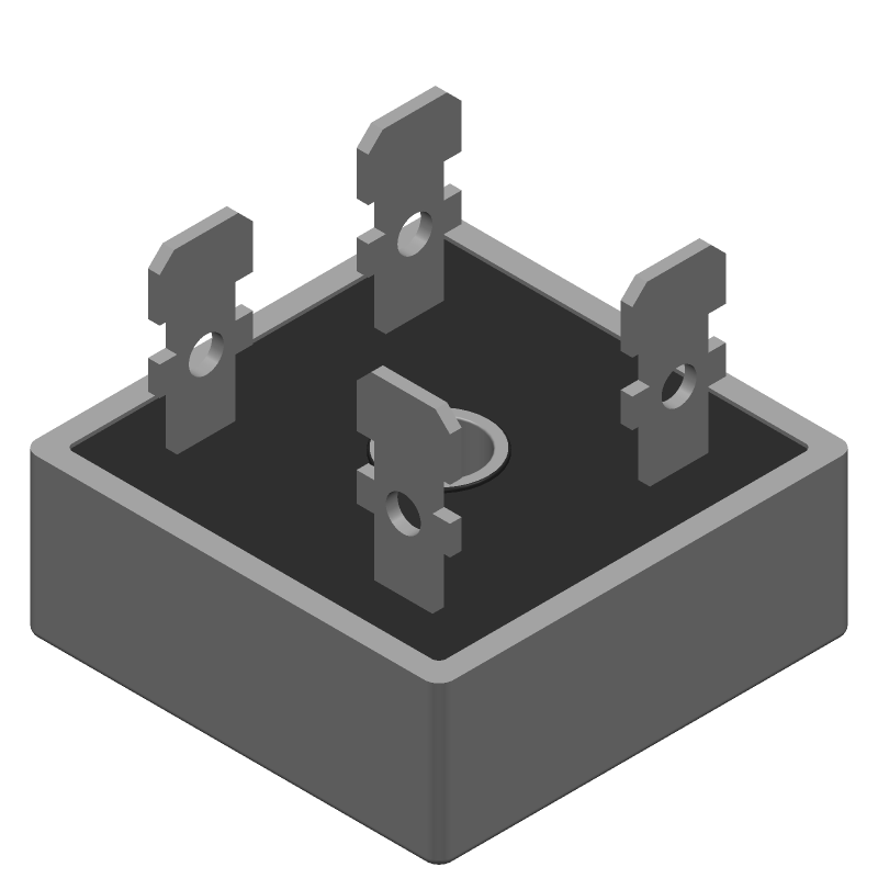
3D Model
Available Download Formats
By downloading CAD models, you agree to our Terms & Conditions and Privacy Policy
Bridge Rectifier Diode, 1 Phase, 15A, 100V V(RRM), Silicon,
Tip: Data for a part may vary between manufacturers. You can filter for manufacturers on the top of the page next to the part image and part number.
KBPC1501 by SPC Multicomp is a Bridge Rectifier Diode.
Bridge Rectifier Diodes are under the broader part category of Diodes.
A diode is a electrical part that can control the direction in which the current flows in a device. Consider factors like voltage drop, current capacity, reverse voltage, and operating frequency when selecting a diode. Read more about Diodes on our Diodes part category page.
| Part # | Distributor | Description | Stock | Price | Buy | |
|---|---|---|---|---|---|---|
|
DISTI #
2675379
|
Farnell | DIODE, BRIDGE RECT, 1-PH, 100V, MODULE RoHS: Compliant Min Qty: 1 Lead time: 20 Weeks, 5 Days Container: Each | 356 |
|
$6.2277 / $11.4196 | Buy Now |
By downloading CAD models, you agree to our Terms & Conditions and Privacy Policy
|
|
KBPC1501
SPC Multicomp
Buy Now
Datasheet
|
Compare Parts:
KBPC1501
SPC Multicomp
Bridge Rectifier Diode, 1 Phase, 15A, 100V V(RRM), Silicon,
Select a part to compare: |
| Part Life Cycle Code | Active | |
| Ihs Manufacturer | MULTICOMP PRO | |
| Reach Compliance Code | unknown | |
| ECCN Code | EAR99 | |
| HTS Code | 8541.10.00.80 | |
| Samacsys Manufacturer | Multicomp Pro | |
| Case Connection | ISOLATED | |
| Configuration | BRIDGE, 4 ELEMENTS | |
| Diode Element Material | SILICON | |
| Diode Type | BRIDGE RECTIFIER DIODE | |
| Forward Voltage-Max (VF) | 1.1 V | |
| JESD-30 Code | S-PUFM-D4 | |
| Non-rep Pk Forward Current-Max | 300 A | |
| Number of Elements | 4 | |
| Number of Phases | 1 | |
| Number of Terminals | 4 | |
| Operating Temperature-Max | 150 °C | |
| Operating Temperature-Min | -55 °C | |
| Output Current-Max | 15 A | |
| Package Body Material | PLASTIC/EPOXY | |
| Package Shape | SQUARE | |
| Package Style | FLANGE MOUNT | |
| Rep Pk Reverse Voltage-Max | 100 V | |
| Surface Mount | NO | |
| Terminal Form | SOLDER LUG | |
| Terminal Position | UPPER |
The recommended PCB layout for optimal thermal performance involves placing the bridge rectifier near the AC input, using a large copper area for heat dissipation, and keeping the PCB traces as short and wide as possible to reduce thermal resistance.
To ensure reliable operation in high-temperature environments, it's essential to provide adequate heat sinking, use a suitable thermal interface material, and follow the recommended derating curves for the device.
The maximum allowable voltage imbalance between the AC input lines is typically 10% to 15% of the rated voltage. Exceeding this limit can lead to reduced performance, overheating, or even device failure.
Yes, the KBPC1501 can be used in a switching power supply design, but it's essential to ensure that the device is properly snubbed to prevent voltage spikes and ringing, which can lead to device failure or reduced lifespan.
The recommended fuse rating for the AC input lines depends on the specific application and the maximum expected inrush current. A general guideline is to use a fuse with a rating of 1.5 to 2 times the maximum expected inrush current.