-
Part Symbol
-
Footprint
-
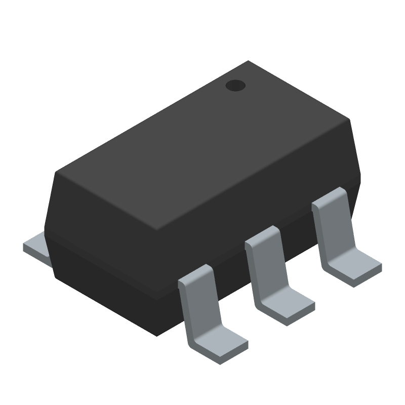
3D Model
Available Download Formats
By downloading CAD models, you agree to our Terms & Conditions and Privacy Policy
HMC313TR
Tip: Data for a part may vary between manufacturers. You can filter for manufacturers on the top of the page next to the part image and part number.
HMC313TR by Analog Devices Inc is an RF/Microwave Amplifier.
RF/Microwave Amplifiers are under the broader part category of RF and Microwave Components.
RF and Microwave Engineering focuses on the design and operation of devices that transmit or receive radio waves. The main distinction between RF and microwave engineering is their wavelength, which influences how energy is transmitted and used in various applications. Read more about RF and Microwave Components on our RF and Microwave part category page.
| Part # | Distributor | Description | Stock | Price | Buy | |
|---|---|---|---|---|---|---|
|
DISTI #
505-HMC313TR-ND
|
DigiKey | IC RF AMP WLAN 0HZ-6GHZ SOT23-6 Min Qty: 500 Lead time: 10 Weeks Container: Tape & Reel (TR) | Temporarily Out of Stock |
|
$2.7489 / $3.0544 | Buy Now |
|
DISTI #
584-HMC313TR
|
Mouser Electronics | RF Amplifier InGaP HBT Gain Block amp SMT, DC - 6 GHz RoHS: Not Compliant | 0 |
|
$2.5600 / $2.9000 | Order Now |
|
|
Analog Devices Inc | InGaP HBT Gain Block amp SMT, Min Qty: 500 Package Multiple: 500 | 85000 |
|
$2.7981 / $5.4900 | Buy Now |
|
DISTI #
26619659
|
Verical | RF Amp Single Broadband Amp 6GHz 5.5V 6-Pin SOT-26 T/R RoHS: Not Compliant Min Qty: 500 Package Multiple: 500 | Americas - 85000 |
|
$2.6000 | Buy Now |
|
|
Rochester Electronics | Wide Band Low Power Amplifier, 0MHz Min, 6000MHz Max RoHS: Not Compliant Status: Active Min Qty: 1 | 500 |
|
$1.9100 / $2.3900 | Buy Now |
|
DISTI #
HMC313TR
|
Richardson RFPD | GAIN BLOCK RoHS: Not Compliant Min Qty: 500 | 0 |
|
$2.3800 / $2.4100 | Buy Now |
By downloading CAD models, you agree to our Terms & Conditions and Privacy Policy
|
|
HMC313TR
Analog Devices Inc
Buy Now
Datasheet
|
Compare Parts:
HMC313TR
Analog Devices Inc
HMC313TR
Select a part to compare: |
| Pbfree Code | No | |
| Rohs Code | No | |
| Part Life Cycle Code | Active | |
| Ihs Manufacturer | ANALOG DEVICES INC | |
| Package Description | SOT-26, 6 PIN | |
| Pin Count | 6 | |
| Manufacturer Package Code | RJ-6 | |
| Reach Compliance Code | not_compliant | |
| ECCN Code | EAR99 | |
| HTS Code | 8542.33.00.01 | |
| Samacsys Manufacturer | Analog Devices | |
| Additional Feature | HIGH RELIABILITY | |
| Characteristic Impedance | 50 Ω | |
| Construction | COMPONENT | |
| Gain | 14 dB | |
| Input Power-Max (CW) | 20 dBm | |
| JESD-609 Code | e0 | |
| Mounting Feature | SURFACE MOUNT | |
| Number of Functions | 1 | |
| Number of Terminals | 6 | |
| Operating Frequency-Max | 6000 MHz | |
| Operating Frequency-Min | ||
| Operating Temperature-Max | 85 °C | |
| Operating Temperature-Min | -40 °C | |
| Package Body Material | PLASTIC/EPOXY | |
| Package Equivalence Code | TSOP6,.11,37 | |
| Power Supplies | 5 V | |
| RF/Microwave Device Type | WIDE BAND LOW POWER | |
| Surface Mount | YES | |
| Technology | BIPOLAR | |
| Terminal Finish | Tin/Lead (Sn/Pb) |
A good PCB layout for the HMC313TR involves keeping the signal paths short, using a solid ground plane, and minimizing the distance between the device and the antenna. It's also recommended to use a 50-ohm microstrip transmission line to connect the device to the antenna.
The HMC313TR requires a bias voltage of 3.3V to 5V on the VCC pin, and a bias current of 30mA to 50mA. It's also important to ensure that the bias voltage is clean and free of noise, and that the device is properly decoupled using capacitors.
The HMC313TR can handle up to 30dBm of output power, but it's recommended to operate it at a maximum of 25dBm to ensure reliable operation and to prevent overheating.
To troubleshoot issues with the HMC313TR, start by checking the bias voltage and current, and ensure that the device is properly connected to the antenna and other components. Use a spectrum analyzer to measure the output power and spectral purity, and check for any signs of overheating or damage to the device.
Yes, the HMC313TR can be used in a push-pull configuration to achieve higher output power. However, this requires careful design and layout to ensure that the two devices are properly matched and biased, and that the output is properly combined.