-
Part Symbol
-
Footprint
-
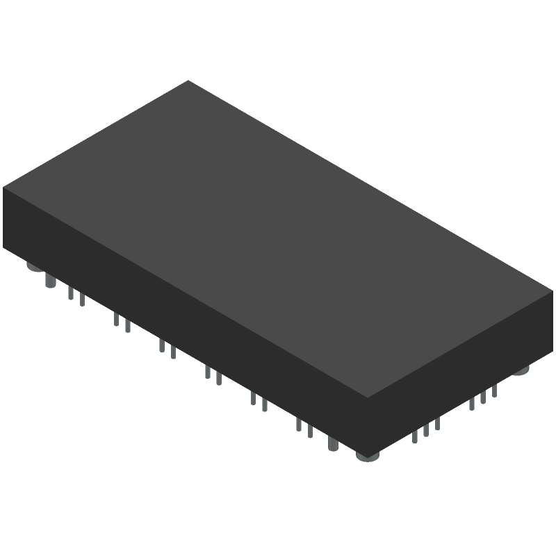
3D Model
Available Download Formats
By downloading CAD models, you agree to our Terms & Conditions and Privacy Policy
Insulated Gate Bipolar Transistor
Tip: Data for a part may vary between manufacturers. You can filter for manufacturers on the top of the page next to the part image and part number.
FS100R17N3E4 by Infineon Technologies AG is an IGBT.
IGBTs are under the broader part category of Transistors.
A transistor is a small semiconductor device used to amplify, control, or create electrical signals. When selecting a transistor, factors such as voltage, current rating, gain, and power dissipation must be considered, with common types. Read more about Transistors on our Transistors part category page.
| Part # | Distributor | Description | Stock | Price | Buy | |
|---|---|---|---|---|---|---|
|
DISTI #
641-FS100R17N3E4
|
Mouser Electronics | IGBT Modules 1700 V, 100 A sixpack IGBT module RoHS: Compliant | 3 |
|
$97.9600 / $115.2800 | Buy Now |
By downloading CAD models, you agree to our Terms & Conditions and Privacy Policy
|
|
FS100R17N3E4
Infineon Technologies AG
Buy Now
Datasheet
|
Compare Parts:
FS100R17N3E4
Infineon Technologies AG
Insulated Gate Bipolar Transistor
Select a part to compare: |
| Pbfree Code | No | |
| Rohs Code | Yes | |
| Part Life Cycle Code | Active | |
| Ihs Manufacturer | INFINEON TECHNOLOGIES AG | |
| Package Description | MODULE-35 | |
| Reach Compliance Code | not_compliant | |
| ECCN Code | EAR99 | |
| Samacsys Manufacturer | Infineon | |
| Case Connection | ISOLATED | |
| Collector-Emitter Voltage-Max | 1700 V | |
| Configuration | BRIDGE, 6 ELEMENTS WITH BUILT-IN DIODE AND THERMISTOR | |
| Gate-Emitter Thr Voltage-Max | 6.4 V | |
| Gate-Emitter Voltage-Max | 20 V | |
| JESD-30 Code | R-XUFM-X35 | |
| Number of Elements | 6 | |
| Number of Terminals | 35 | |
| Operating Temperature-Max | 150 °C | |
| Operating Temperature-Min | -40 °C | |
| Package Body Material | UNSPECIFIED | |
| Package Shape | RECTANGULAR | |
| Package Style | FLANGE MOUNT | |
| Peak Reflow Temperature (Cel) | NOT SPECIFIED | |
| Polarity/Channel Type | N-CHANNEL | |
| Power Dissipation-Max (Abs) | 600 W | |
| Reference Standard | UL APPROVED | |
| Surface Mount | NO | |
| Terminal Form | UNSPECIFIED | |
| Terminal Position | UPPER | |
| Time@Peak Reflow Temperature-Max (s) | NOT SPECIFIED | |
| Transistor Application | POWER CONTROL | |
| Transistor Element Material | SILICON | |
| Turn-off Time-Nom (toff) | 1240 ns | |
| Turn-on Time-Nom (ton) | 280 ns | |
| VCEsat-Max | 2.3 V |