-
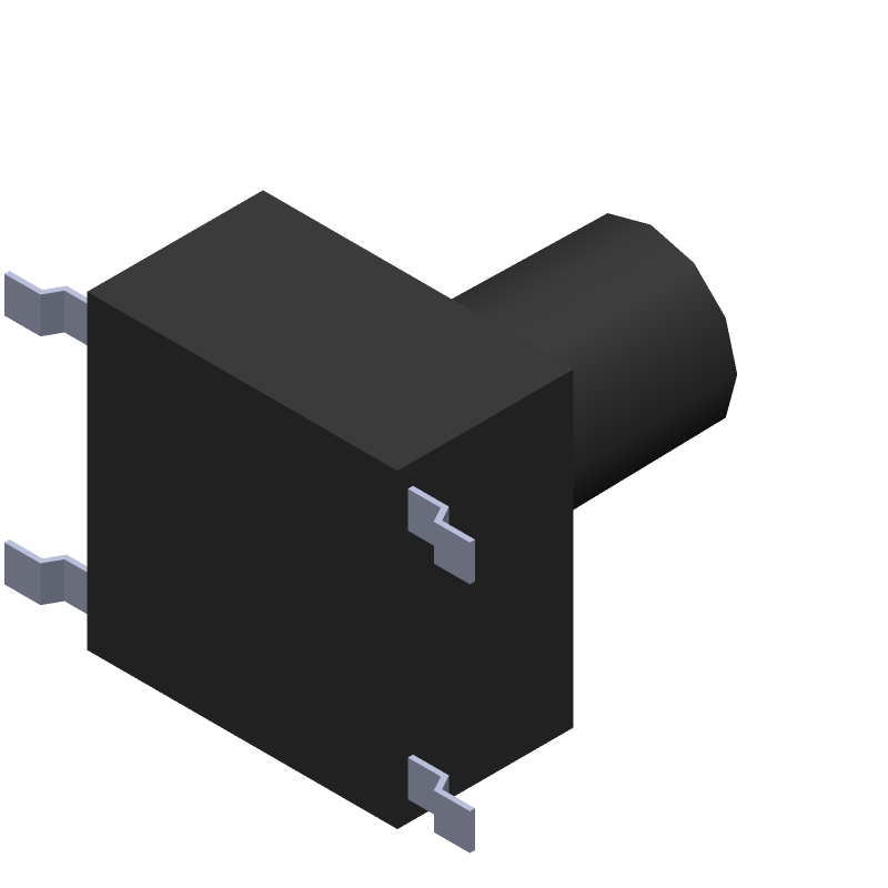
3D Model
Available Download Formats
By downloading CAD models, you agree to our Terms & Conditions and Privacy Policy
Keypad Switch
Tip: Data for a part may vary between manufacturers. You can filter for manufacturers on the top of the page next to the part image and part number.
CS11028.0F260 by CIT Relay & Switch is a Keypad Switch.
Keypad Switches are under the broader part category of Switches.
Electrical switches are binary devices that control the flow of current in a circuit by either allowing or preventing the flow of electrons. Read more about Switches on our Switches part category page.
| Part # | Distributor | Description | Stock | Price | Buy | |
|---|---|---|---|---|---|---|
|
DISTI #
2449-CS11028.0F260CT-ND
|
DigiKey | SWITCH TACTILE SPST-NO 0.05A 50V Min Qty: 1 Lead time: 7 Weeks Container: Cut Tape (CT), Digi-Reel®, Tape & Reel (TR) |
6395 In Stock |
|
$0.1867 / $0.3800 | Buy Now |
By downloading CAD models, you agree to our Terms & Conditions and Privacy Policy
|
|
CS11028.0F260
CIT Relay & Switch
Buy Now
Datasheet
|
Compare Parts:
CS11028.0F260
CIT Relay & Switch
Keypad Switch
Select a part to compare: |
| Rohs Code | Yes | |
| Part Life Cycle Code | Contact Manufacturer | |
| Ihs Manufacturer | CIT RELAY & SWITCH | |
| Reach Compliance Code | compliant | |
| ECCN Code | EAR99 | |
| HTS Code | 8536.50.90.40 | |
| Samacsys Manufacturer | CIT Relay & Switch | |
| Actuator Material | POLYAMIDE | |
| Actuator Travel | 0.25 mm | |
| Body Breadth | 6 mm | |
| Body Height | 3.5 mm | |
| Body Length or Diameter | 6 mm | |
| Center Contact Material | PHOSPHOR BRONZE | |
| Center Contact Plating | SILVER | |
| Circuit Configuration | 1X1 | |
| Contact Current(DC)-Max | 0.05 A | |
| Contact (DC) Max Rating R Load | 0.05A@50VDC | |
| Contact Resistance | 0.05 mΩ | |
| Contact Voltage(DC)-Max | 50 V | |
| Dielectric Withstand Volts | 250VRMS V | |
| Electrical Life | 100000 Cycle(s) | |
| End Contact Material | PHOSPHOR BRONZE | |
| End Contact Plating | SILVER | |
| Housing Material | NYLON | |
| Insulation Resistance | 100000000 Ω | |
| Mounting Feature | SURFACE MOUNT-STRAIGHT | |
| Number of Switches | 1 | |
| Operating Force-Max | 2.55 N | |
| Operating Temperature-Max | 85 °C | |
| Operating Temperature-Min | -40 °C | |
| Packing Method | TAPE AND REEL | |
| Surface Mount | NO | |
| Switch Action | MOMENTARY | |
| Switch Function | SPST | |
| Switch Type | KEYPAD SWITCH | |
| Terminal Material | BRASS | |
| Termination Type | SOLDER |
The recommended PCB layout and spacing for the CS11028.0F260 can be found in the CIT Relay & Switch application note AN-101, which provides guidelines for proper PCB design and layout to ensure reliable operation and minimize electromagnetic interference (EMI).
To ensure proper driving and control of the CS11028.0F260, it is recommended to use a suitable driver circuit that can provide the required voltage and current to the relay coil. The driver circuit should also include protection components such as diodes and resistors to prevent back-EMF and voltage spikes.
The maximum switching frequency of the CS11028.0F260 is not explicitly stated in the datasheet, but it is typically limited by the relay's mechanical switching time and the driver circuit's capabilities. As a general guideline, the relay can be switched at frequencies up to 10 Hz, but this may vary depending on the specific application and operating conditions.
The CS11028.0F260 relay requires a coil voltage of 5V and a coil current of 30mA. To handle these requirements, it is recommended to use a voltage regulator and a current-limiting resistor in the driver circuit to ensure the relay coil is properly powered and protected from overvoltage and overcurrent conditions.
The CS11028.0F260 relay is designed to operate in a temperature range of -40°C to 85°C and a humidity range of 40% to 90% RH. It is also recommended to operate the relay in a clean and dry environment, away from exposure to moisture, dust, and other contaminants that may affect its performance and reliability.