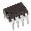
Part Details for DS1004C-303 by Maxim Integrated Products
Results Overview of DS1004C-303 by Maxim Integrated Products
- Distributor Offerings: (2 listings)
- Number of FFF Equivalents: (0 replacements)
- CAD Models: (Request Part)
- Number of Functional Equivalents: (0 options)
- Part Data Attributes: (Available)
- Reference Designs: (Not Available)
Tip: Data for a part may vary between manufacturers. You can filter for manufacturers on the top of the page next to the part image and part number.
DS1004C-303 Information
DS1004C-303 by Maxim Integrated Products is a Delay Line.
Delay Lines are under the broader part category of Logic Components.
Digital logic governs the behavior of signals in electronic circuits, enabling complex decisions based on simple binary inputs (yes/no). Logic components perform operations from these signals. Read more about Logic Components on our Logic part category page.
Price & Stock for DS1004C-303
| Part # | Distributor | Description | Stock | Price | Buy | |
|---|---|---|---|---|---|---|
|
DISTI #
2156-DS1004C-303-ND
|
DigiKey | 5-TAP HIGH SPEED DELAY LINE Min Qty: 258 Lead time: 1 Weeks Container: Bulk MARKETPLACE PRODUCT |
392 In Stock |
|
$1.1600 | Buy Now |
|
|
Rochester Electronics | DS1004 5-Tap High Speed Silicon Delay Line RoHS: Not Compliant Status: Obsolete Min Qty: 1 | 392 |
|
$0.9520 / $1.1200 | Buy Now |
Part Details for DS1004C-303
DS1004C-303 CAD Models
DS1004C-303 Part Data Attributes
|
|
DS1004C-303
Maxim Integrated Products
Buy Now
Datasheet
|
Compare Parts:
DS1004C-303
Maxim Integrated Products
Silicon Delay Line, 1-Func, 5-Tap, True Output, CMOS, PDIP8, 0.300 INCH, PLASTIC, MS-001AB, DIP-8
Select a part to compare: |
| Pbfree Code | No | |
| Rohs Code | No | |
| Part Life Cycle Code | Obsolete | |
| Ihs Manufacturer | MAXIM INTEGRATED PRODUCTS INC | |
| Part Package Code | DIP | |
| Package Description | 0.300 INCH, PLASTIC, MS-001AB, DIP-8 | |
| Pin Count | 8 | |
| Reach Compliance Code | not_compliant | |
| HTS Code | 8542.39.00.01 | |
| Factory Lead Time | 4 Weeks | |
| Family | CMOS | |
| JESD-30 Code | R-PDIP-T8 | |
| JESD-609 Code | e0 | |
| Length | 9.375 mm | |
| Logic IC Type | SILICON DELAY LINE | |
| Number of Functions | 1 | |
| Number of Taps/Steps | 5 | |
| Number of Terminals | 8 | |
| Operating Temperature-Max | 70 °C | |
| Operating Temperature-Min | ||
| Output Polarity | TRUE | |
| Package Body Material | PLASTIC/EPOXY | |
| Package Code | DIP | |
| Package Shape | RECTANGULAR | |
| Package Style | IN-LINE | |
| Peak Reflow Temperature (Cel) | 240 | |
| Programmable Delay Line | NO | |
| Qualification Status | Not Qualified | |
| Seated Height-Max | 4.572 mm | |
| Supply Voltage-Max (Vsup) | 5.25 V | |
| Supply Voltage-Min (Vsup) | 4.75 V | |
| Supply Voltage-Nom (Vsup) | 5 V | |
| Surface Mount | NO | |
| Technology | CMOS | |
| Temperature Grade | COMMERCIAL | |
| Terminal Finish | TIN LEAD | |
| Terminal Form | THROUGH-HOLE | |
| Terminal Pitch | 2.54 mm | |
| Terminal Position | DUAL | |
| Time@Peak Reflow Temperature-Max (s) | 20 | |
| Width | 7.62 mm |
